Todays modern machinery is the most sophisticated and advanced in all of history.
But it would not exist if it were not for the humble gear.
Similarly, mechanical machines could not function without gears.

The earliest examples of gears date from China in the 4th century BC.
The gears can be viewed at the Luoyang Museum of Henan Province.
In Europe, the earliest preserved gears date from around 150 BC.
They were found in the Antikythera Mechanism, which was designed to calculate astronomical positions.
Most famously, Archimedes developed gears during that period.
Today, there are various types of gears that all have their own benefits and uses for numerous applications.
So, gear yourself up to find out more about eight of the most commonly used gears.
But first things first.
How are gears actually made?
In this article
Gear Machines
Gears enable machines to work.
But machines enable gears to be manufactured.
The best machinery for manufacturing gears is Computer Numerical Control gear machines.
If you are looking to make gears, you should consider getting a CNC gear machine.
A gear hobber is one machine that will come in very handy.
It makes teeth by cutting into a workpiece.
The machine works by rotating the two spindles shafts and cutting into the material.
Various materials can be used, including metal,wood, and plastic.
it’s possible for you to get both vertical and horizontal gear hobbers.
Gear hobbers can typically create gears of up to ten feet.
Buying a CNC gear machine does not have to cost the earth either.
Now, let us take a look at some of the most commonly used gear types.

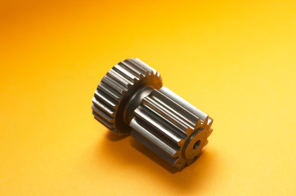
A spur gear consists of a cylinder with teeth that project radially.
The teeth are not straight-sided.
Instead, they are usually involute, and sometimes cycloidal.
The edge of each tooth is straight, though, and is aligned parallel to the rotation axis.
The gears must be fitted to parallel shafts if they are to mesh together properly.
And with spur gears, no axial thrust is generated by the tooth loads.
This throw in of gear can be quite noisy when used at high speeds in machinery.
But spur gears are excellent for moderate and low-speed applications.
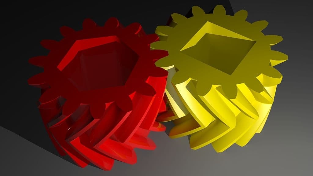
Helical Gears
Also known as dry-foxed gears, helical gears are more refined versions of spur gears.
Helical gears can mesh in either crossed or parallel orientations.
Crossed orientations have non-parallel shafts.
When the gears are in that configuration, they are sometimes called skew gears.
For a crossed or skew configuration, the gears must have a normal pitch and the same pressure angle.
However, the handedness and the helix angle can vary.
As for helical gears with parallel orientations, the shafts are simply parallel to one another.
Parallel-oriented helical gears are the most common form of helical gears.
Due to the gradual engagement of helical gear teeth, it means the gears run smoothly and quietly.
Therefore, helical gears are typically used for high-speed applications, unlike spur gears.
Helical gears are also often used for applications in which large power transmission and noise abatement are important.
However, that is not a problem for double helical gears.
In fact, it can be an advantage because it results in less axial thrust.
Another disadvantage of helical gears is they have a greater chance of causing sliding friction between the teeth.
Though, that problem can be treated by using a lubricant with additives.
The gear is ideal for overcoming the issue of axial thrust that standard helical gears experience.
Double helical gears use a double set of teeth that are slanted in different directions.
Due to the design of the helical gear, the arrangement cancels the total axial thrust.
That is because each half of the double helical gear thrusts in opposing directions.
A double helical gear also reduces the potential need for thrust bearings.
There are two potential arrangements for the rotational directions of helical gears.
The second is an unstable arrangement.
It involves both axial forces being directed away from the gears center.
With a stable arrangement, a total corrective force is generated.
There is also a special key in of double helical gear called the herringbone gear.
A herringbone gear does not have a groove in the middle like many double helical gears have.
With a herringbone gear, the two mirrored gears are joined to make a V shape.
The gear somewhat resembles a lantern, hence the lantern gear alias.
It also resembles a birdcage, hence the cage gear name.
Cage gears are very efficient.
They also do not get clogged up like other gears.
Dirt can fall straight through instead of becoming trapped and increasing the gears wear.
Instead, the method involves simply drilling holes and inserting the rods.
Also, bear in mind that a cage gear should always be driven by a gearwheel.
It should not be used as the driver.
However, cage gears were not originally favored by conservative clockmaker.
Many traditional domestic clock movements use cage gears.
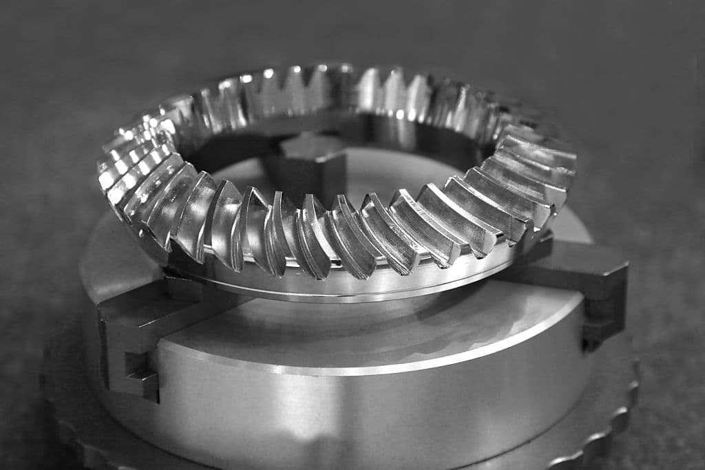
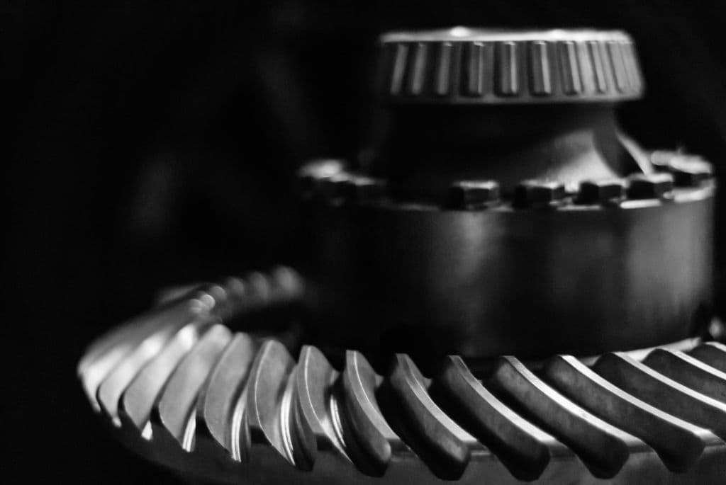
Bevel Gears
Imagine a circular cone with a cut-off tip.
That is pretty much what a bevel gear looks like.
When two bevel gears mesh together, their invisible vertices have to occupy the same point.
At that point, the axes intersect to form a non-straight angle between the shafts.
That angle can be anything other than 180 or 0 degrees.
Straight bevel gears are typically used at speeds of under 5 m/s.
A specific bang out of bevel gear that is commonly used is the spiral bevel.
Gleason spiral bevels are examples of the former and Curvex and Oerlikon are examples of the latter.
Spiral bevel gears can also be manufactured as epicycloids with constant tooth depth, such as Klingelnberg Cyclo-Palloid gears.
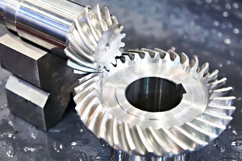
Hypoid Gears
Hypoid gearsare basically spiral bevel gears with one difference: the shaft axes do not intersect.
Although hypoid gears look conical, they are actually hyperboloids of revolution compensating for the offset shaft.
A hypoid gear is almost always operated with shafts of 90 degrees.
Compared to a spiral bevel gear, a hypoid gears pinion can be designed with fewer teeth.
That results in the gear ratio being able to reach 60:1 or even higher.
That is one reason why hypoid gears are most commonly used in motor vehicle drive trains.
Non-hypoid gears are not suitable for motor vehicle drive trains because they generate too much vibration and noise.
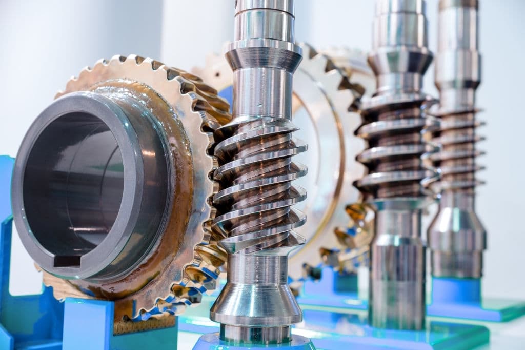
Using a worm-and-gear set is an easy and compact way to achieve a high torque and low-speed gear ratio.
For instance, helical gears are typically limited to gear ratios of under 10:1.
With worm-and-gear sets, you could reach a gear ratio of up to 500:1.
A worm gear is actually a key in of helical gear.
Due to those attributes, worm gears have screw-like qualities.
Worm gears can have just one tooth or several teeth.
Worm gears with one tooth are known as single-threads or single-starts.
Gears with more than one tooth are known as multiple-threads or multiple-starts.
You should know that with a worm-and-gear set, the worm will always be able to drive the gear.
But if the gear tries to drive the worm, it could be unsuccessful.
It will not always be unsuccessful, but it can be; especially if the lead angle is small.
Worm gears can be right or left-handed.
That basically means the gears partially overlap.
To do that, both gears must be made concave and joined at a saddle point.
That is known as double-enveloping, or cone-driving.
Self-locking worm-and-gear sets are available, as well.
That can be advantageous when you better position a mechanism by turning the worm and hold that position.
That kind of mechanism can be found in some musical instruments.
Worms are often used in music boxes, too.
Magnetic Gears
This one is rather different from the other gears on this list.
Instead of having teeth like standard gears, a magnetic gear uses magnets.
As the two opposing magnets come closer, they repel.
So, when they are placed on two rings, the two opposing magnets act like gear teeth.
At the same time, magnetic gears provide the same motion ratio as traditional gears and are noise-free.
Magnetic gearsare mostly used for very specific applications.
Magnetic gears have lots of other advantages.
Typically, magnetic gear systems use permanent magnets but they can sometimes use electromagnets.
The latter is usually reserved for specialized cases that involve changeable gear ratios.
The cogs can also be intermeshed to improve the coupling.
